Publicerad den Lämna en kommentar

Antennas on the front line of anti-jamming

Protection from jamming has emerged as the key concern of of both national and organizational/corporate infrastructures. The world abounds in bad actors, and systems based on GNSS signals are uniquely vulnerable. A basic component of any anti-jamming (AJ) strategy is a shielded antenna. An upcoming webinar, June 27, gives a primer and several advanced looks at developing such an antenna-based AJ campaign. Register here for the complimentary webinar.

Anti-Jam antennas use techniques, such as nulling or beam-forming, to mitigate the effects of interfering signals. (Image: Orolia)

Anti-jam antennas use techniques, such as nulling or beam-forming, to mitigate the effects of interfering signals. (Image: Orolia)

Controlled reception-pattern antennas (CRPAs) are advanced, multi-element antenna solutions that protect a GNSS/GPS receiver from jamming sources. When combined with antenna electronics, they form an anti-jam antenna system (AJAS). These systems utilize several available technologies and vary in the number of elements.

CRPAs will play an increasing role in the GPS/GNSS landscape. Initially developed in the military domain, they are now entering the civilian market and are poised to bring their benefits to the fields of aerospace, ground transportation, autonomous driving and others. Engineers working with GNSS systems that employ CRPAs and multi-element antennas need special test systems since they need to replicate very specific test conditions that are impossible with live signals.

The June 27 webinar, “Advanced Simulation Test Systems for Controlled Reception Pattern Antennas,” will cover the basics of AJAS and CRPA, and the methods used to test them. Details on simulation system configurations, calibration techniques, and use case examples will also be presented.

These complex antenna systems require advanced GNSS simulation equipment in order to be designed and validated, as well as to test their performance. These test systems come in two forms — an anechoic chamber system used to test the CRPA antenna over the air, and a wavefront simulator used to test the antenna electronics with a direct cable connection.

Webinar speakers:

Photo: Spectracom

Perdue

Lisa Perdue, Product Manager, Orolia. Perdue is an expert in testing critical GPS and GNSS systems. She has trained hundreds of engineers and technicians who are responsible for high-reliability positioning, navigation and timing applications. She took a lead role in the development of the first GNSS Vulnerability Test System and speaks widely on the topic at many industry conferences.

Headshot: Stéphane Hamel

Hamel

Stéphane Hamel, Director, Testing, Orolia. With a career spanning more than 20 years in engineering test and RF, Hamel has developed many innovative and large-scale products to test semiconductor devices, radios and GNSS receivers. In 2014, he founded Skydel, now part of Orolia. Hamel is one of the architects behind the Skydel SDX GNSS simulator.

Dean Kemp, Defense Segment Manager, NovAtel.

Moderator: Alan Cameron, GPS World.

Register here for the free June 27 webinar.

Publicerad den Lämna en kommentar

Tell us the future: State of the Industry survey open for input

What technical and business challenges are getting your attention this year?

What are the most important benefits of, and the key challenges posed by, new modernized GNSS signals? How are you driving business in today’s economy?

What issues are you concerned about?  What solutions hold the most promise for positioning, navigation and timing (PNT) in challenged and indoor environments — regardless of which technology provides them?

We want to know, and so does the rest of the industry.

What is the key challenge for positioning and navigation in the wireless and consumer space? (Source: GPS World 2018 State of the GNSS Industry survey)

What is the key challenge for positioning and navigation in the wireless and consumer space? (Source: GPS World 2018 State of the GNSS Industry survey)

GPS World is asking PNT professionals about the developing technology frontiers, the state of their business, the economic climate for products and services, driving market factors, the effects of jamming, the Issue of the Year — and more! Please give us your opinions in the 2019 State of the Industry survey. It should take less than 10 minutes, and your responses are confidential.

A handful of lucky participants drawn at random will win TWO $100 gift cards good (virtually) anywhere.

Complete the survey by June 30. Then look for a complete report of our findings in the September issue of GPS World.

Thank you for taking the time to share your feedback and help us improve our magazine content, industry awareness — and your own business!

While asking questions that have appeared in past State of the Industry surveys, to reveal industry changes that have taken place over the last five years, the 2019 Survey presents these new issues for your consideration:

• With multiple constellations, signals and services now beginning to emerge, what are the challenges to keeping open and seamless access to these in the international marketplace ? 

• Among the many benefits of modernized signals, which is the most important in your field of work?

• Among the key challenges in utilizing modernized signals, which gets most of your attention? 

The question above offers such answer choices as: increases die size without ability to increase chip cost; longer code sequences are difficult to acquire; increases RAM/ROM; increases number of RF channels; increases number of digital channels; higher CPU processing required; and software complexity with many signal types. 

What one word would you use to describe your company’s No. 1 opportunity to grow in 2020? 

What one word would you use to describe your company’s No. 1 obstacle to growth in 2020?

Overall, the 2019 Survey covers such topics as:

  • Technology Trends.  PNT is rapidly diversifying among a number of complementary technologies, as GNSS looks to inertial, lidar, laser, cellular, WiFi and other beacons, signals of opportunity, low-Earth orbit satellite constellations and more. Different market sectors have, naturally, different requirements, and these lead to different integration combinations. Where do you see the most promise?
  • The Global Economy and how it affects business in your sector. Customers’ availability of capital to invest is top-of-mind for most industry professionals, whether designers, manufacturers, integrators, suppliers/dealers, or end users.
  • Industry Confidence in the road ahead. Sound business navigation requires a fluid, responsive combination of technology, capital, investment, and often most important, human capital. .
  • Issues of Concern. To what extent do industry leaders take into account the following as well as further factors?
    • Pricing and competitive issues;
    • GNSS jamming, spoofing, other RF interference;
    • Developing compatibility and interoperability of GNSS: GPS, GLONASS, BeiDou, Galileo;
    • Advantages and drawbacks of other positioning and navigation technologies.

The survey report, complete with insightful articles and infographics, will appear in the September issue. Look for it!

Please click here to begin the survey.

Publicerad den Lämna en kommentar

Robinson helicopter tested as UAV for heavy lifts

A Robinson R22 helicopter was converted by UAVOS to an unmanned drone. UAVOS — which specializes in the design, development and manufacturing of unmanned vehicles and autopilot systems — successfully completed in-air programmed missions with the unmanned helicopter.

The first flight this spring of the modernized helicopter lasted more than one hour and was performed in a fully self-piloted mode, reaching an altitude of up to 2,200 feet (670 meters). During the flight, all scheduled tests were performed including fully automatic take-off, enroute flight and landing. The tuning of UAV control settings was completed as well.

The converted R22-UV is serving as a platform for research and testing for commercial UAV options. For instance, upcoming test flights will include cargo delivery of up to 330 pounds (150 kg) in automatic mode. Flights with a duration of 6+ hours using additional fuel tanks and a payload for monitoring the land surface are also planned.

Besides that, UAVOS is planning to check operational limitations of the UAV during night flights and flights under severe weather conditions. A top priority is testing the possibility of using spraying equipment and to see whether R22-UV could serve agricultural purposes.

Components installed. The UAVOS components installed in R22-UV helicopter included autopilot, servo drives, sensor system and additional backup power supply. During the conversion, the aircraft electrical system was upgraded, manual control was removed, the fuselage was altered for servo drives and components of the automatic control system installation. In addition, the pilot seats were removed and replaced by additional fuel tanks.

Powered by a gasoline engine, the unmanned R22-UV helicopter is able to deliver cargo or carry payload with a total weight of up to 330 pounds (150 kg) with a maximum take-off weight of 1,400 pounds (635 kg).

Heavy payloads. The converted aircraft has a practical ceiling of 13,780 feet (4,200 meters) and has a top speed of 189 kph. The UAV is designed to carry high-precision, heavy professional equipment 88 pounds (40 kg and more) for a wide variety of missions including lidar, synthetic aperture radar, heavy optical equipment or gas analyzers.

The R22-UV can be operated in the regions without airfields, under severe weather conditions and during night-time, in the conditions with high stress risk for a pilot. The converted helicopter is useful for oil and gas companies that need to deliver cargo to hard-to-reach places, or where chemicals hazardous to humans are spread on the fields and forests. Operational limits for high-altitude flights and missions in heavy turbulence and high mountain regions should be defined after appropriate testing.

The project was carried out jointly with King Abdulaziz City for Science and Technology (KACST), a scientific government institution of the Kingdom of Saudi Arabia.

Publicerad den Lämna en kommentar

Abom launches military/industrial goggles with GNSS/INS

Logo: Abom

Abom, a company that designs sophisticated commercial goggles, has launched new augmented reality (AR) goggles.

Designed for safety, industrial and military markets, Abom’s P3 augmented reality goggles feature accurate tracking of orientation, velocity and positioning using IMU/GPS-GNSS/INS receiver capability.

Other features include 3D spatial mapping and tracking, integrated VX Inc. CNED display technology, and an array of integrated image sensors and advanced embedded electronics. The goggles’ stereoscopic dual displays have an ultra-high-brightness output with adjustable control and 1080p output.

The goggles are optimized with a military-ballistics-rated lens (MIL-PRF 32432A) that complies with the Military Compliance Eye Protection (MCEP) program, meeting many challenging elements of the U.S. Army’s IVAS specification (HUD 3.0).

For industrial applications, the P3 also meets ANSI Z87.1+ high-mass impact rating and IP-55 ingress protection against water and dust, which opens the door for supporting National Safety Council technology initiatives and requirements for meeting extreme IP-67 rating compliance.

The P3 goggles are field-use ready and designed for extreme environmental durability and cold-weather climate conditions where demanding ruggedized performance is critical. It has advanced thermal image sensors, and embedded within the Goggle Chassis is an ultra-high-performance depth camera supported by two infrared cameras optimized for low-light conditions up to 10 meters.

The goggles incorporate Abom’s patented ultra-low power thin-film technology, making it impossible for fog to survive on the inner surface of the eyewear, according to the company.

“Abom’s award-winning heated goggle technology, now military approved, has made integration and optimization with immersive, augmented reality display technology the perfect solution for highly ruggedized extreme use-cases that exceed industry standards for both quality and performance,” said Jack Cornelius, Abom CEO.

“Abom’s development partner for the P3 Goggle, VX Inc., has pushed the limits of mechanical and electrical engineering design performance,” Cornelius said.

Publicerad den Lämna en kommentar

Diving into digital mapping history with OpenStreetMap

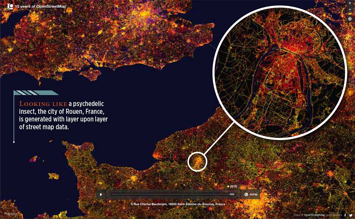
A European region in 2015. (Image: OpenStreetMap)

A European region in 2015. (Image: OpenStreetMap)

A tool developed by Mapbox explores “10 years of OpenStreetMap.” During that decade,hundreds of thousands of people mapped 25 million miles of roads in every country in the world.

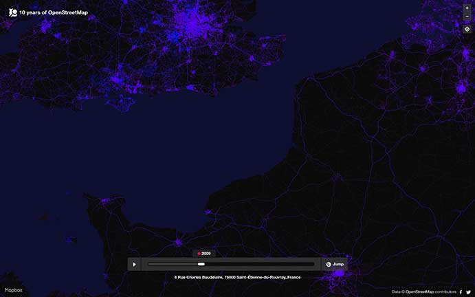
The internet tool uses a slider to show the data change over time. You can see additions and edits as they come online over the decade — a fascinating look at the intricate information that has been compiled. When a user drags the slider to the left, it’s easy to see how scant the information was only a few years into OpenStreetMap’s existence (the image at right shows the same European region in 2009 as the image at the top in 2015).

The same European region in 2009 as the image at the top in 2015. (Image: OpenStreetMap)

The same European region in 2009 as the image at the top in 2015. (Image: OpenStreetMap)

After GPS and GNSS, OpenStreetMap ranks high in the movement to make geographic information accessible. OpenStreetMap is a community-driven project to create the most detailed, correct and current open map of the world.

When Steve Coast began the project in 2004, map data sources were few, and largely controlled by private companies and the government. Coast changed the rules by creating a wiki-like resource of the entire globe, which everyone could use. Today, 5.2 million people use OpenStreetMap.

OpenStreetMap democratized mapping: all a contributor needed was time and a computer connection to add data about their country or their neighborhood. Besides GNSS, contributors use aerial imagery and low-tech field maps to verify that OSM is accurate and up to date. Others dedicate their energies to humanitarian projects, including disaster response following the Haiti hurricane and aiding South Sudan and Syrian refugees.

Publicerad den Lämna en kommentar

Anatomy of a centimeter-level precise point positioning service

By Markus Brandl, Xiaoming Chen, Herbert Landau, Carlos Rodriguez-Solano and Ulrich Weinbach

This article updates a July 2012 feature in GPS World, “Real-Time Extended GNSS Positioning: A New Generation of Centimeter-Accurate Networks.”

The Trimble CenterPoint RTX correction service, enabling centimeter-level absolute positioning around the world without the need for RTK reference-station infrastructure, is now available to many users, including integrators of professional high-precision equipment and consumer products such as in the automotive sector. Access is provided via a software library compatible with any GNSS device. The corrections now contain detailed integrity information for safety-critical applications.

The RTX infrastructure is made up of approximately 120 globally distributed RTX reference stations. Receivers at these stations transmit measurement data at 1 Hz to the RTX server centers, where the correction data is computed. For redundancy purposes, multiple servers in the United States and Europe are operated. A failsafe architecture avoiding any single point of failure in the processing chain has produced a very high availability of corrections. Today the system supports GPS, GLONASS, Galileo, BeiDou and QZSS satellites. It is a multi-frequency system supporting two or more frequencies for each satellite system.

The correction stream is available to users using L-band signals broadcast via geostationary satellites and IP connections. The L-band transmitted RTX data stream uses a bandwidth of 600–2400 baud, and a highly compressed data format with a resolution of 1 millimeter, with an average latency of 8 seconds in L-band mode and 5 seconds in IP mode. The data stream is encrypted via an Advanced Encryption Standard (AES) with a key length of 256 bits to guarantee safe transmission. Data transmission integrity is assured with a 32-bit cyclic redundancy check attached to every message. The RTX correction stream provides information on satellite position, satellite clock, ionospheric and tropospheric models, and code and phase biases.

The orbit determination is done in real time using a reduced dynamic approach with dynamic models and exploiting the accuracy of the phase measurements after ambiguity fixing. Based on the computed orbits, the satellite clocks are estimated at 1 Hz, where integer ambiguity fixing is performed for the different satellite systems.

Next, a single-layer global ionospheric model is computed and represented through spherical harmonics. There are currently two areas with a denser network than the global network; these cover Europe and the mainland U.S. with more than 1,000 base stations. Using these stations, regional ionospheric and tropospheric models are computed, which then provide a fast convergence (RTX-Fast service).

The satellite position and clock information has centimeter accuracy and allows the client to compute precise point positioning (PPP) with carrier-phase ambiguity resolution. Table 1 shows service accuracy.

Table 1. Accuracy of the RTX corrections from more than three years (June 2015–July 2018) of residuals computation in the European RTX-Fast network. (Table data: authors)

Table 1. Accuracy of the RTX corrections from more than three years (June 2015–July 2018) of residuals computation in the European RTX-Fast network. (Table data: authors)

Once the ambiguities are resolved, the position solution is accurate to a few centimeters. The global RTX-Standard service provides convergence times of 7 minutes to 20 centimeters (cm) horizontal error (95%) and to 2.5 cm (95%) in 13 minutes as shown in Figure 2. The regional RTX-Fast service (U.S., Europe) provides convergence times of less than a minute with centimeter accuracy. The warmstart convergence time is approximately 13 seconds.
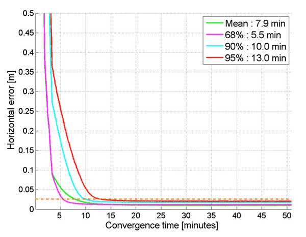
Figure 2. Global convergence of RTX out of 52 globally distributed stations covering one month of data. (Image: Trimble)

Figure 2. Global convergence of RTX out of 52 globally distributed stations covering one month of data. (Image: Trimble)

The accuracies specified are achievable with precise Trimble GNSS positioning hardware. For integration into non-Trimble devices, an RTX software library is offered, which gives the user real-time access to the individual data in the RTX correction stream. For use of this library in safety-critical systems such as advanced driving-assisted systems (ADAS) or semi-automated driving, this library was certified to follow the ASIL-B ISO 26262 standard and the automotive ASPICE standard. This library is available for easy integration into third-party applications.

In addition to the real-time RTX solution, a web-based post-processing solution is available for public use free of charge. It is possible to upload static Trimble or RINEX files to the server, post-process the measurement data, and retrieve a precise position in various coordinate frames.

Service integrity is continuously monitored at independent stations from the RTX tracking networks in Europe and the US. The integrity of the service is provided at the correction data domain. The integrity monitoring part of the RTX system minimizes the risk due to events such as unplanned satellite maneuvers or wrong broadcast ephemeris; satellite signal or clock anomalies; ionospheric storms; or problems in transmitting the RTX correction stream.

The monitoring stations compute phase observation residuals (with ambiguity fixing) using the station measurements and the received RTX corrections. These residuals represent the actual errors of the corrections as seen by the monitoring stations at the line-of-sight (Table 1). The thresholds at which corrections are considered as faulty are the following: 0.5 m + QI (quality indicator) for orbit + clock corrections and regional tropospheric models, and 1.0 m + QI for regional ionospheric models.

The integrity monitoring consists of two steps (Figure 1): a pre-broadcast check, where potentially faulty corrections are detected and filtered out before leaving the computing server, and a post-broadcast check, where additional errors in the transmission channel are detected and alarms are issued to the users.
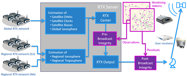
Figure 1. Generation and transmission of RTX global and regional corrections, including pre- and post-broadcast integrity monitoring. (Image: Trimble)

Figure 1. Generation and transmission of RTX global and regional corrections, including pre- and post-broadcast integrity monitoring. (Image: Trimble)

Integrity flags and alarms are constantly inserted into the correction stream and output by the RTX client library. The integrity information notifies clients of the presence of integrity monitoring and provides timely alerts in case of detected correction-data integrity violations. The time-to-alert limit goals are 17 seconds for L-band transmission and 13 seconds for IP transmission for the RTX service.

The RTX corrections includes quality indicators. In particular, the quality indicator for the satellite clock includes a “DoNotUse” flag to indicate potential problems with the given satellite. This flag prevents the use of the satellite for positioning when received by the user. The quality indicators of the corrections are indeed a first integrity layer. In 2017 the pre-broadcast integrity monitoring was added to act as a second layer. In 2019, with the addition of the post-broadcast integrity monitoring, a third integrity layer was added to the RTX correction data stream.

The RTX system provides access to centimeter-level corrections allowing centimeter positioning on a global basis. RTX-Fast services are available in Europe and the U.S. with pre- and post-broadcast integrity monitoring currently being deployed.


The authors are engineers with Trimble Terrasat GmbH, Germany.

Publicerad den Lämna en kommentar

Using consumer-grade sensors for precise positioning

By Urs Niesen, Jubin Jose, Xinzhou Wu, Qualcomm Technologies Inc.

Emerging automotive applications require reliable but at the same time low-cost positioning solutions. In this paper, we present such a solution by fusing the measurements from several consumer-grade sensors using a tightly coupled centralized filter.

The sensors used are a single-frequency GNSS receiver providing GPS and GLONASS pseudoranges and GPS carrier-phase measurements, a micro-electro-mechanical (MEMS) inertial measurement unit (IMU), a monocular camera, wheel-speed and steering-angle sensors.

We also employ vehicular constraints, integrated as pseudo-measurements. The centralized fusion architecture allows sensor cross-calibration and improves outlier detection. The filter runs in real time on the target platform, producing pose estimates at 30 Hz. Through extensive experimental evaluations, we demonstrate positioning accuracies of sub-meter 95-percentile horizontal errors even in GNSS-challenged deep-urban scenarios.

Conflicting Requirements. Accurate positioning is a requirement for several emerging vehicular applications such as advanced driver-assistance systems (ADAS) and autonomous driving. Positioning solutions for these applications face two competing constraints. To be technically viable, the computed position estimate needs to be reliable in scenarios ranging from open sky to deep urban, with less than 1-meter 95-percentile horizontal error as an often-mentioned target. To be economically viable, the system needs to be built from consumer-grade components.

We reconcile these conflicting requirements by fusing measurements from several low-cost sensors into a single pose estimate using one centralized extended Kalman filter (EKF). A multi-constellation single-frequency GNSS receiver provides GPS pseudorange and carrier-phase measurements and GLONASS pseudorange measurements. These are combined in a tightly coupled integration architecture with a consumer-grade MEMS IMU used to produce the reference navigation solution.

Tight integration enables outlier rejection directly for the raw GNSS measurements. This is crucial in deep-urban scenarios, since many or most raw GNSS measurements could be outliers in these conditions. We use a monocular camera and vehicular sensors, providing four wheel-speed measurements and a steering-angle measurement, as additional aiding sensors.

Constraints. Finally, vehicular constraints are integrated as pseudo-measurements. These sensors have very different noise sources and failure modes, which allows cross-calibration and improves failure and outlier detection. Given the tightly coupled integration in a single EKF, the filter state is quite large and can reach more than 100 dimensions. Despite its size, we are able to run the filter in real time and on target, producing pose outputs at a rate of 30 Hz.

We report the result of extensive experimental evaluations in different scenarios ranging from open sky with good satellite visibility to deep urban with long stretches of no or only limited satellite visibility. In each of these scenarios, we obtain the target accuracy of sub-meter 95% horizontal positioning error.

We show that, in the benign open-sky scenarios, GPS and IMU sensors are sufficient to achieve the target accuracy. However, in challenging deep-urban scenarios, all the integrated sensors are required to attain reliable sub-meter positioning performance.

Sensors and Components. We use Qualcomm SiRFstarV 5e B02 GNSS chipset, a low-cost commercial GNSS product, connected to a NovAtel GPS-702-GG dual-frequency GPS+GLONASS Pinwheel antenna, the only component not consumer-grade, to separate impact of a specific antenna on performance. We plan to evaluate low-cost antennas in the future. We use a TDK InvenSense low-cost MEMS 6-axis IMU (MPU-6150) and a vehicle interface with vehicle sensors through the controller area network bus. Accurate timestamping for tightly coupling sensor measurements is provided by a custom sensor sync board. The processor is a Qualcomm Snapdragon 820 automotive platform for real-time computation. (Qualcomm SiRFstar and Qualcomm Snapdragon are products of Qualcomm Technologies, Inc. and/or its subsidiaries.)

This paper was presented at ION-GNSS+ 2018.
.

Publicerad den Lämna en kommentar

Auterion enables Impossible Aerospace to launch new US-1 drone for first responders

Photo: Impossible Aerospace

Photo: Impossible Aerospace

Auterion and Impossible Aerospace has announced their partnership and collaboration to bring to market the US-1 UAV, which has a two-hour flight time.

Auterion is the provider of Auterion Enterprise PX4, an open-source-based, enterprise operating system for drones. Impossible Aerospace is Silicon Valley-based drone manufacturer on a mission to assemble the highest performance electric aircraft.

“During critical public safety incidents, real-time intelligence from a UAV is extremely important. This is why the two-hour flight time of the US-1 is a clear necessity.” said Spencer Gore, CEO of Impossible Aerospace. “We turned to Auterion for software because their operating system is auditable and trusted for government applications.”

“Public safety organizations can now field a drone with government solicited, cyber-secure and trusted software that enables the drone to stream real-time footage to a command center,” said Kevin Sartori, co-founder of Auterion. “Choosing Auterion and its open-source, open-standards approach will greatly simplify the integration of the US-1 into the IT-infrastructure of public safety organizations.”

Thousands of professional drone pilots and businesses around the world count on open-source flight control software PX4, which was created by Auterion co-founder Lorenz Meier in 2011 and has evolved into a global developer community. Similar to Red Hat, Auterion builds the open-source infrastructure so that drone manufacturers can go to market faster with new products flying trusted software.

The US-1 quadcopter made its public safety debut in February with a California-based police force. The drone gives police agencies a new category of assets that sit between lower-end drones and police helicopters. This enables a wider usage of aerial imagery and reduces the cost for first responders at the same time.

Publicerad den Lämna en kommentar

CHC Navigation opens NA headquarters in Arizona

Photo: CHC Navigation

Photo: CHC Navigation

Shanghai-based GNSS technology and solutions company Shanghai Huace Navigation Technology Ltd. — known as CHC Navigation — has opened a North American subsidiary, CHC Navigation USA Corporation, in Scottsdale, Arizona.

CHC Navigation was established in 2003 and was ranked as one of China’s top GNSS and RTK technology and solutions companies in 2017. It has customers in more than 100 countries worldwide and has been providing GNSS and RTK products and solutions to the US marketplace since 2009.

The establishment of a North American head office in Scottsdale illustrates CHC Navigation’s ongoing commitment to expanding its products, services and customer support in the US and North American marketplaces.

CHC USA will warehouse, sell and service from Scottsdale all of its products to its dealer and OEM network of customers across North America. With the new U.S. presence, CHC USA will be able to respond more quickly to its dealer and customer order requests and service requirements.

CHC USA specializes in CORS GNSS base-station infrastructure, deformation monitoring, surveying and mapping. With new 3D lidar scanning and hydrographic unmanned survey vessels launching later this year, CHC USA’s North American office and team members will continue to focus on ensuring a great customer experience.

“On the heels of strong CHC Navigation growth in the US in 2018, the time was right to establish a domestic US sales and service office and warehouse with a local team of positioning industry professionals,” said George Zhao, CEO of CHC Navigation. “Our U.S. and Canadian customers have been very supportive of CHC Navigation over the years and our focus will continue to be on providing industry leading products and services to our valued North American dealers and customers,” added Phil Gabriel, President of CHC Navigation USA.

Publicerad den Lämna en kommentar

Topcon’s Sitelink 2.0 offers Haul Truck application

Sitelink 2.0. (Photo: Topcon)

Sitelink 2.0. (Photo: Topcon)

Topcon Positioning Group is offering a new edition of its real-time 3D job site monitoring and management system — Sitelink 2.0. The update includes a new pay-as-you-go point-based service model, new features to Sitelink Support Desk, as well as a new Haul Truck application.

Version 2.0 includes a newly redesigned web portal that features a consumption-based “Service Point” investment model.

“We are introducing a completely new way to service our customers that allows them to take advantage of a pay-as-you-go account-based system rather than year-long pre-paid subscription-based plans,” said Murray Lodge, senior VP, Construction. “With no expiration date on the Service Points, contractors can be assured their investment will be protected in their personal account and allocated when it best suits their needs.”

Also, new to the service includes remote configuration functionality in Support Desk. It allows Topcon support personnel to directly access and configure receiver components on connected machines, while simultaneously retaining an active remote session of the 3D-MC machine control software.

“We have made support more efficient with less downtime for operators with our team having the ability to go straight into the configuration settings for receivers and make adjustments, minimizing work stoppage on the site,” said Lodge.

The latest version also includes a new Topcon Haul Truck application, which utilizes an Android or iOS app that can be installed on a phone or tablet. It is designed to provide a complete and easy-to-use cloud-based, haul management and reporting system with real-time visibility.

“The new Haul Truck app provides productivity statistics for each haul, including the counts, average distances and the time it takes to complete the process — all within a geofenced pickup site and unloading zone. It is simple to use — drivers come onto the site, quickly enter basic info and get to work. With 3D map imagery, operators can view where the load is being picked up and the path it takes to unload and return, and it automatically records for reporting,” Lodge said.