Publicerad den Lämna en kommentar

EOS Positioning helps Haiti achieve clean drinking water

Haiti Outreach is on a mission is to bring clean drinking water to 100% of Haitian communes. The non-profit organization is using EOS Positioning’s Arrow Gold GNSS receiver to transform how water access is addressed.

In the Western Hemisphere’s poorest nation, poverty and corruption have stifled development. But Haiti Outreach is using geospatial software and donations to ensure every household has access to clean drinking water. Their technology includes mWater, EPANET, and Arrow Gold with Atlas.

In this video, you’ll hear from Haiti Outreach Director Neil Van Dine and Eos Positioning Systems CTO Jean-Yves Lauture on the importance of combining spatial strategy with a human element.

In Haiti 95% of unprotected springs are contaminated with E. coli, with 48% of water infrastructure across 50 communes delivering water contaminated with E.coli (Haiti Outreach 2018 study). For 22 years, a nonprofit called Haiti Outreach has tried to increase access to clean water by drilling wells for Haitian communities (called communes).

Haiti Outreach tried drilling new wells, but that didn’t solve the problem. The answer is education. “It’s all about creating a transformation in the way we think,” Van Dine said. “Water is free, but somebody has to maintain the well, replace parts, and so on in the long term. All those things cost money.”

Achieving a 50-cents per household fee for maintenance, Haiti Outreach still needed to know if everyone in Haiti had access to clean drinking water. The organization needed to know the location of every household in relation to water sources. They also needed to know if these water sources were clean, contaminated, functioning or broken.

Outreach decided to use the open-source hydraulic-modeling software EPANET, from the U.S. government, and hired mWater to build an integration. By running population-density overlays in mWater, it was possible to identify where there were enough households (25) to create a revenue stream to support a new well. With 100 households, the revenue could support a new in-home water-distribution network.

Photo: Haiti Outreach

Photo: Haiti Outreach

They also used Android phones and Arrow Gold with Atlas. By pairing the Arrow Gold with Atlas, they were able to get decimeter accuracy. (Atlas is a satellite-based differential correction service.)

“The Android phones got about 10 meters of accuracy on their own,” Haiti Outreach fieldwork coordinator Micki Johns said. “But the Arrow Gold with Atlas got us within that decimeter range.”

Data collected in mWater went into EPANET to simulate water pressure and flow.

Haiti Outreach used the findings to develop a community action plan (CAP). The CAP prioritized cleaning contaminated sources and ranked contaminated sources by the highest number of people who would benefit from a decontamination.

Learn more about the program here.

Publicerad den Lämna en kommentar

Terra Drone launches AI-based UAV solution for power lines

Photo: Terra Drone

Photo: Terra Drone

Terra Drone Corporation has launched a new UAV and artificial-intelligence (AI)-based solution designed for maintenance of power transmission and distribution equipment.

The solution was developed based on market gaps identified after inspecting more than 90,000 kilometers of power lines beyond visual line of site (BVLOS) throughout the world.

Acquired data is automatically processed and analyzed by artificial intelligence algorithms trained to detect crossovers at the bottom of transmission lines, buildings and construction machinery.

The system identifies rust on bolts, loosening and missing tower parts, bird’s nests and more. It then generates a smart report highlighting areas that require action. The error (identified anomaly) detection system is accurate up to 92.5%.

The algorithm for an area is developed through a process identifying anomalies in a training data set of 1,500 images. This allows for a custom solution to be created for the end client where all pertinent anomalies are identified and reported.

The development and training of the algorithm only need to be completed once for a particular type of asset and can be implemented easily at different locations on similar assets.

With such a high-precision algorithm, the productivity of AI processing allows for fast actionable results to be provided to clientele. Clients also have the ability to identify the appropriate security protocols for data storage in either a cloud-based or on-premises storage environment. These protocols can then be implemented in a custom client-specific solution.

Loosening and missing tower parts identified by high-accuracy detection system (Photo: Terra Drone)

Loosening and missing tower parts identified by high-accuracy detection system (Photo: Terra Drone)

Power transmission and distribution companies must conduct periodic inspections of power line infrastructure to ensure reliable electric power distribution, although the conventional methods of deploying ground staff or low-flying helicopters to complete the inspections, they are typically cost-prohibitive. Conventional helicopter and boots-on-the-ground service also pose HSE concerns with low flying helicopters and people working in the field. UAV service and AI inspection can aid in minimizing HSE concerns by reducing the number of workers in the field and eliminate low level manned helicopter missions.

This solution has been built from ground up with the aim to simplify and streamline the maintenance work for transmission and distribution facilities.

Publicerad den Lämna en kommentar

Richard Wiegmann joins VertiGIS as president and CEO

Richard Wiegmann as President and CEO. (Photo: VertiGIS)Photo:

Richard Wiegmann as President and CEO. (Photo: VertiGIS)

The Board of Directors for VertiGIS, a geographic information systems (GIS) software and solutions provider, appointed Richard Wiegmann as president and CEO.

Wiegmann began his new role Aug. 1.

VertiGIS comprises Esri Platinum Partners AED-SICAD, Geocom Informatik and Latitude Geographics (Geocortex), and aED-SYNERGIS, Dynamic Design and SynerGIS GIS & FM.

Wiegmann, 49, lives with his family near Frankfurt. He brings extensive executive experience in software and services to the operational management of VertiGIS and was one of the company’s original board members. Previously, he was CEO and Chief Commercial Officer of Sabre Hospitality Solutions, which in 2016 acquired Trust – International Hotel Reservation Services.

“I’m excited to join the team at VertiGIS, and see so much potential for us in the GIS market and beyond,” Wiegmann said.”By bringing together major GIS companies, we can leverage the expertise of our employees and the strong cooperation of partners like Esri to provide our customers the best-in-market solutions for their businesses, and ensure they offer long-term stability and planning security.”

VertiGIS’ product portfolio is used by more than 12,000 users in private-sector companies and government agencies. Current product brands include UT for ArcGIS, the 3A product line, Geocortex, GEONIS, ConnectMaster, GeoOffice, WebOffice and ProOffice.

“I look forward to further developing our existing products and services with a great team, and bringing new ideas together in this highly interesting growth market,” Wiegmann added.

Publicerad den Lämna en kommentar

Trimble to acquire GIS company Cityworks for EAM expansion

Photo: Cityworks

Photo: Cityworks

Trimble has signed a definitive agreement to acquire privately held Azteca Systems LLC (Cityworks), a provider of enterprise asset management (EAM) software for utilities and local government.

Cityworks’ solutions address the global challenges associated with maintaining and replacing aging utility, transportation and public assets and infrastructure.

The transaction is expected to close in the fourth quarter of 2019, subject to customary closing conditions and expiration of the waiting period u

nder the Hart-Scott-Rodino Antitrust Improvements Act. Financial terms were not disclosed.

Cityworks, based in Sandy, Utah, was launched in 1996 and provides a powerful and flexible office, cloud and mobile EAM software solution that is used by more than 700 utilities and local governments. EAM is a key technology and system of record relied on by organizations to address a wide range of applications in infrastructure development, maintenance and permitting.

Cityworks is a leader in the mid-sized utility and local government market segments in North America and its solutions address organizations of all sizes with deployments serving some of the largest cities in the U.S.

The Cityworks acquisition will expand Trimble’s strategy by adding an EAM software platform to its existing utilities and local government capabilities, which include mobile, IoT and infrastructure lifecycle solutions. The combination will provide a comprehensive digital platform — with real-time asset intelligence, workflows and analytics — for transforming the way governments and utilities prioritize infrastructure maintenance and construction investments.

In addition, the acquisition will enable Cityworks to leverage Trimble’s global footprint in multiple industries.

Together, Trimble and Cityworks will provide an expanded solutions portfolio to their partner network of architecture, engineering and construction (AEC) firms and software system integrators.

Customers will benefit from integrated solutions that will enable them to realize improved infrastructure performance, increased productivity and better return-on-investment associated with infrastructure construction and operation.

“Cityworks is a pioneer in developing software to address the global challenges associated with managing aging, critical infrastructure,” said Steve Berglund, president and CEO of Trimble. “Trimble has a long history of transforming industries by combining technologies and providing full solutions that help customers measure, assess, design and construct infrastructure at scale. With Cityworks, we now expand our solutions portfolio enabling customers to manage and optimize the performance of their assets across the entire infrastructure lifecycle.”

“Trimble is an ideal match for Cityworks and the work we aspire to do in helping utilities and communities improve public infrastructure management. Joining Trimble is strategic, providing exciting growth opportunities and new opportunities for innovation,” said Brian L. Haslam, founder, president and CEO of Cityworks. “Cityworks as a Trimble company will accelerate our GIS-centric public asset management approach and allow us to increase the impact and value our solutions deliver to customers.”

The Cityworks business will be reported as part of Trimble’s Resources and Utilities Segment.

Publicerad den Lämna en kommentar

NGS releases beta version of NCAT 2.0

My last column highlighted the next phase of the National Geodetic Survey’s (NGS) GPS on Bench Marks program; that is, the development of the 2022 transformation model. It provided web links to material explaining the new GPS on Bench Marks program. NGS continues to update this site so I would encourage users to periodically check the site for updates. At the time of this column, the site was updated on Sept. 13. See the box titled “GPS on Bench Mark Web Page.”
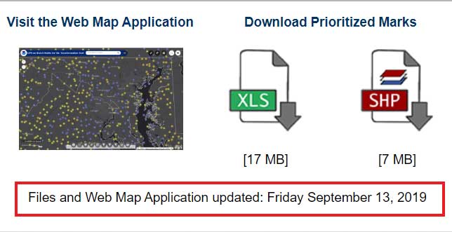
GPS on Bench Mark Web Page

Image: National Geodetic Survey

Image: National Geodetic Survey

This column is going to focus on the newly released beta version of NCAT 2.0, which includes the new beta version of VERTCON 3.0. See the box titled “NGS Product Updates.”
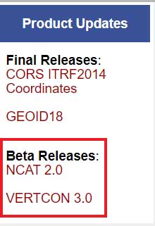
NGS Product Updates

Image: National Geodetic Survey

Image: National Geodetic Survey

On Sept. 24, NGS sent an NGS News Update through its data delivery system. See the box titled “NGS News Announcement of VERTCON 3.0.”

NGS News Announcement of VERTCON 3.0
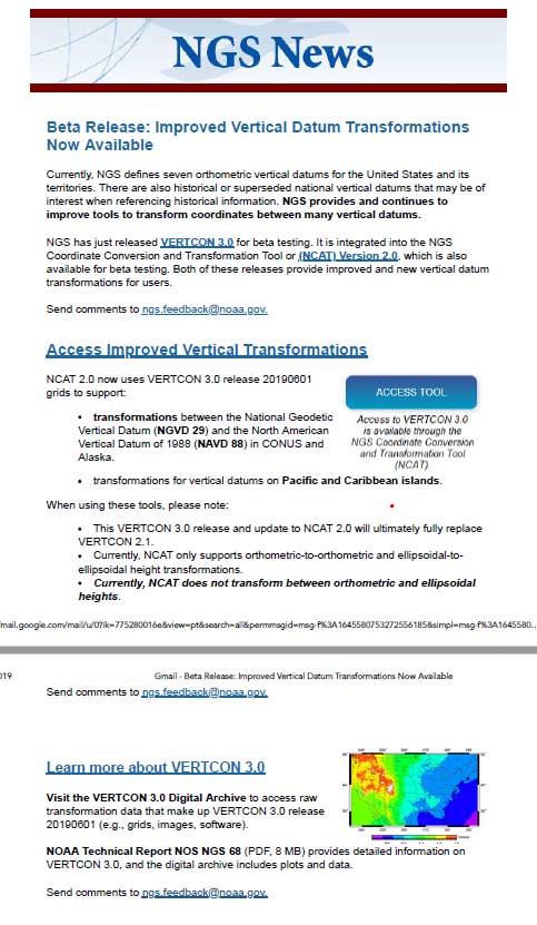
Image: National Geodetic Survey

Image: National Geodetic Survey

As a side note, anyone can sign up for NGS News announcements by clicking on the button titled “Subscribe for email notifications” on the left side of NGS Home Page. See the box titled “Subscribe for NGS Email Notifications “
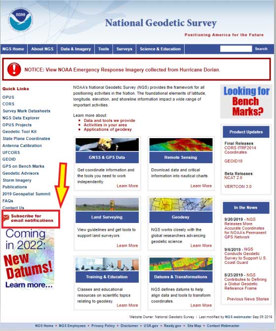
Subscribe for NGS Email Notifications

Image: National Geodetic Survey

Image: National Geodetic Survey

At this time, there are four NGS subscription services available:

  1. NGS News
  2. NGS Webinar Series
  3. NGS Training
  4. NGS GPS on Bench Marks.

For more information on how to sign up for each of the subscription series click here. (See the box titled “NGS Subscription Web Page.”)
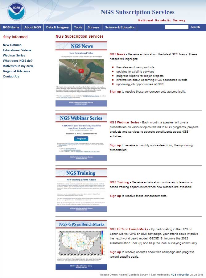
NGS Subscription Web Page

Image: National Geodetic Survey

Image: National Geodetic Survey

Why is NGS Updating VERTCON now?

First, NGS published a technical document that provides a brief history of previous versions of the VERTCON model and the technical details of the new beta VERTCON 3.0 model. The report is titled “NOAA Technical Report NOS NGS 68,The VERTCON 3.0 Project” and can be downloaded here.

NGS decided to update the existing VERTCON tool with two primary purposes in mind:

  1. to support as many of the vertical datums of the NSRS as possible, and
  2. to prepare users for the new North American-Pacific Geopotential Datum of 2022 (NAPGD2022).

NGS plans include incorporating the new VERTCON 3.0 model into its integrated products and services. See the box titled “Excerpt from NOAA Technical Report NOS NGS 68, The VERTCON 3.0 Project: Motivation for VERTCON 3.0.”

As a matter of fact, the beta version of VERTCON 3.0 is included in an updated beta version of the NGS Coordinate Conversion and Datum Transformation Tool (NCAT). This column will provide examples converting NGVD 29 heights to NAVD 88 heights using the new beta versions of NCAT and VERTCON.

Excerpt from NOAA Technical Report NOS NGS 68, The VERTCON 3.0 Project: Motivation for VERTCON 3.0

The greatest driver for VERTCON 3.0 was the pending release of NAPGD2022, expected in late 2022. As part of that release, NGS intends to release grids to transform between existing vertical datums and NAPGD2022. As the build software used to create all previous versions of VERTCON was no longer available, it was decided (like NADCON; see Smith and Bilich, 2017) to completely recreate the entire suite of VERTCON build software.

However, unlike horizontal datums, the history of vertical datums at NGS is, as mentioned earlier, quite limited. As a transformation can only exist if two datums are released in a region, this limits what expansion to VERTCON 2.1 might be possible. Nonetheless, most regions at least had “Local Tidal” heights published by NGS as well as some other official vertical datum of the NSRS, so a decision to support transformation in these regions was made.

Knowing that such a re-build would replace VERTCON 2.1, the new project and its build software were designated from the beginning as “VERTCON 3.0”.

Other expected advantages with this project were the chance to update documentation and the delivery of the transformations, through incorporation into newly integrated products and services like the NGS Coordinate Conversion and Datum Transformation Tool (NCAT, available at https://www.ngs.noaa.gov/NCAT/) and VDatum (available at https://vdatum.noaa.gov/).

Users can access the VERTCON 3.0 model by clicking on the VERTCON 3.0 link on NGS Home Page. It will direct the user to this website.
See box titled “VERTCON 3.0 Web Site.” The user can also download the Technical Report from this site.
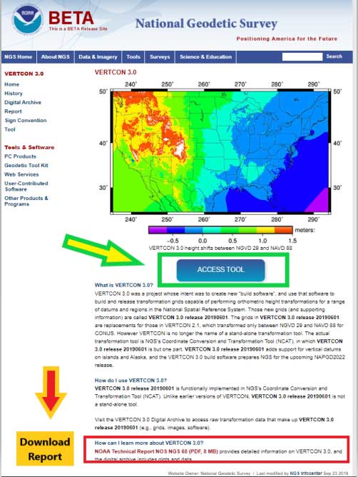
VERTCON 3.0 Web Site

Image: National Geodetic Survey

Image: National Geodetic Survey

Clicking on the “Access Tool” button” connects the user to the Beta NCAT website. See box titled “Beta NCAT Website.” Two links have been highlighted in the box: “About Conversion Tool” and “Horizontal+height.”
The default values for the beta NCAT are “Horizontal” and “Geodetic lat-lon.” If the user wants to use the VERTCON 3.0 option, he or she must click on the button “Horizontal+height.”
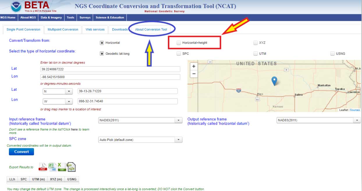
Beta NCAT Website

Image: National Geodetic Survey

Image: National Geodetic Survey

Clicking on the “About Conversion Tool” provides a brief description of the tool. I’ve highlighted a section in the description that should be pointed out to users. See the box titled “NCAT Brief Description” and the statement below.

“Please note that, although either orthometric or ellipsoidal heights can be used as inputs to NCAT, at this time NCAT does not convert between orthometric and ellipsoidal heights. Only orthometric-to-orthometric and ellipsoidal-to-ellipsoidal height transformations are currently possible in NCAT.”
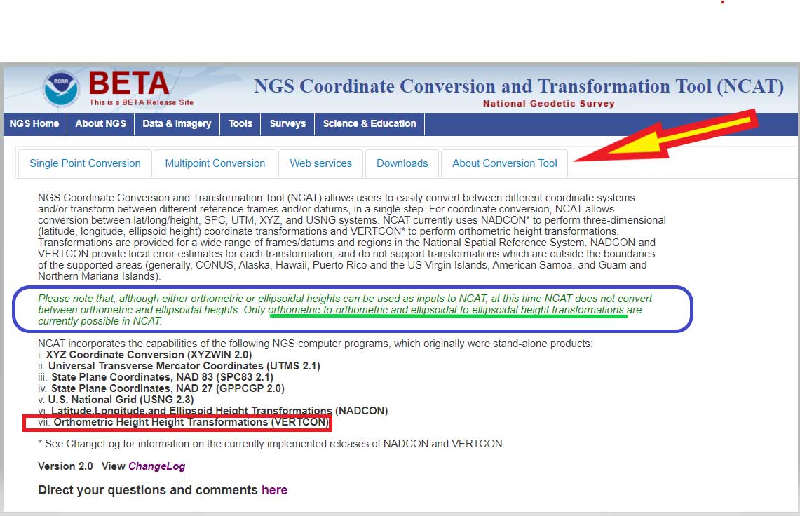
NCAT Brief Description

Image: National Geodetic Survey

Image: National Geodetic Survey

What this means is that you can convert, at this time, stations located in the Conterminous United States and Alaska from NGVD 29 to NAVD 88, and from NAVD 88 to NGVD 29. In order to convert from one orthometric height system to another, you have to click on another button. I’ve highlighted the button in the box titled “Single Point Conversion – Horizontal+height.” Clicking on the button “Horizontal+height” initiates another set of buttons under the section titled “select a height.” There are two options ellipsoid or orthometric. The ellipsoid button is the default option. If you want to convert a height from the NGVD 29 datum to the NAVD 88 datum the user needs to select the button titled “orthometric.”

Single Point Conversion – Horizontal+height
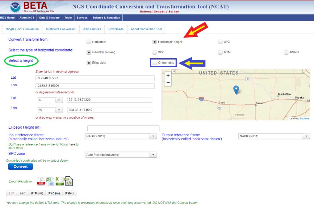
Image: National Geodetic Survey

Image: National Geodetic Survey

The box titled “Select a Height Option” is a screenshot of the site after the user clicks the “Orthometric height option. The user can now select the input and output vertical datums. The input and output datum options are highlighted in the box.

Select a Height Option
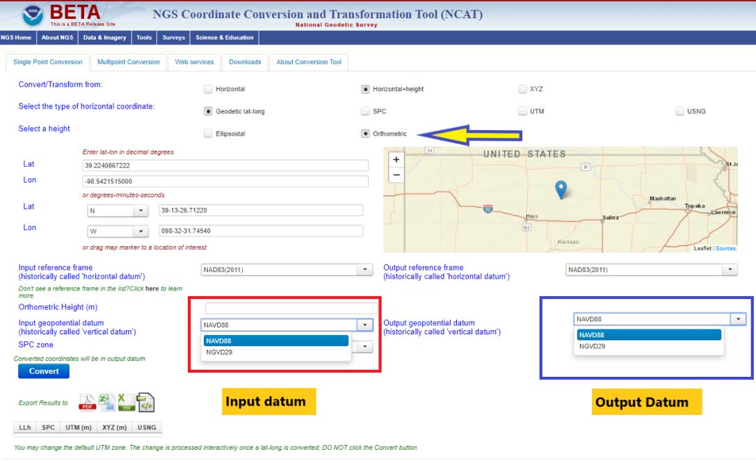
Image: National Geodetic Survey

Image: National Geodetic Survey

Once you select the input and output vertical datums, you need to input the latitude and longitude of the station, select the reference frame, and input an orthometric height value to be converted. You must enter an orthometric height that you want to be converted. The box titled “Converting from NGVD 29 to NAVD 88 – Input Parameters” provides an example for station RU 36 (PID FA1337) located in Rutherford County, North Carolina.

Converting from NGVD 29 to NAVD 88 – Input Parameters
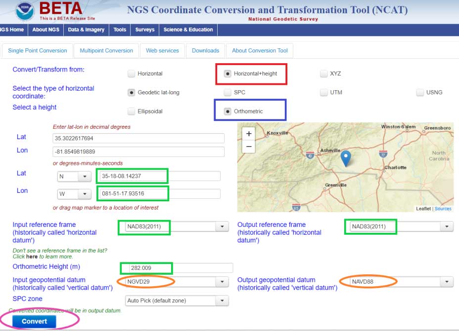
Image: National Geodetic Survey

Image: National Geodetic Survey

After you enter your input parameters, click on the button titled “Convert.” The box titled “Converting from NGVD 29 to NAVD 88 – Output Solution” provides the output from Beta NCAT tool. The input height and output heights are highlighted in the box. The solution also provides an estimate of the accuracy of the value (SigOrthoht).

Converting from NGVD 29 to NAVD 88 – Output Solution
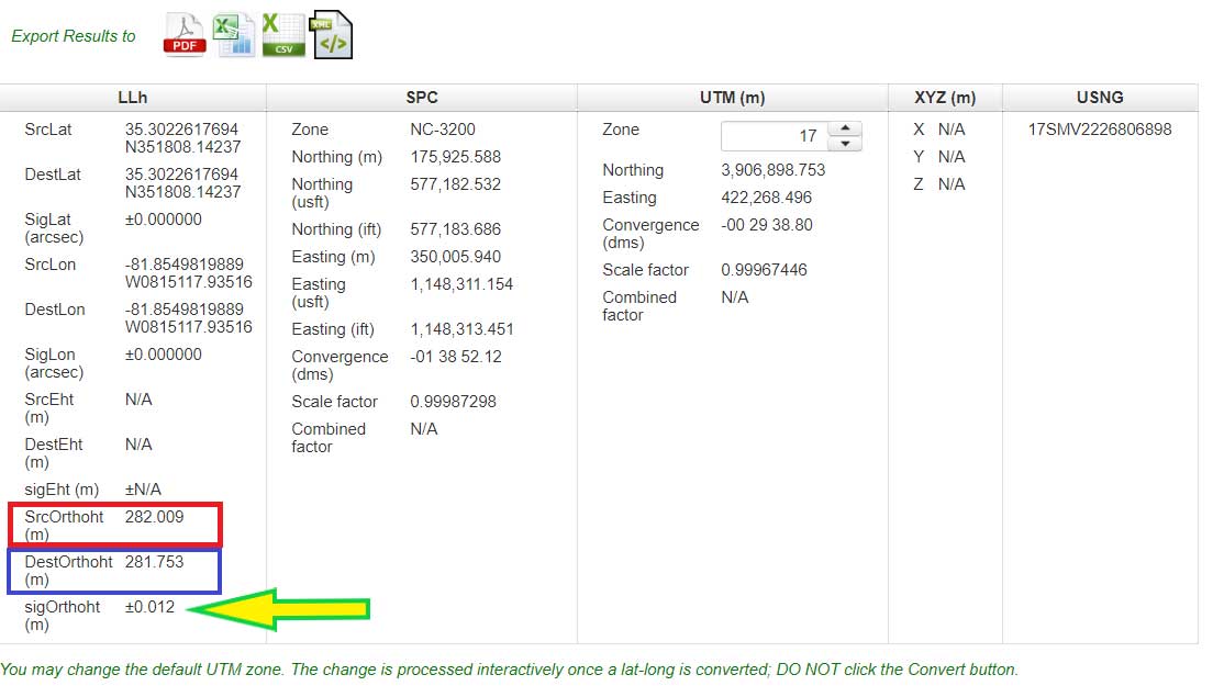
Image: National Geodetic Survey

Image: National Geodetic Survey

The published information for RU 36 (PID FA1337) is listed in the box titled “Published Information for Station RU 36.” The NGVD 29 height converted to a NAVD 88 orthometric height from the Beta NCAT tool agrees with the superceded NAVD 88 height to within a couple of millimeters (281.753 m minus 281.755 m = -0.002 m). Saying that, the station was superseded with a GNSS-derived orthometric height and the difference is a little larger, 281.79 m minus 281.753 m = 0.037 meters. I’m not saying that there’s anything wrong with the conversion model, I’m only highlighting that, in this case, it agrees with the NAVD 88 leveling-derived heights even though that station has been superceded by a GNSS-derived orthometric height. Users should be aware of this.

Published Information for Station RU 36
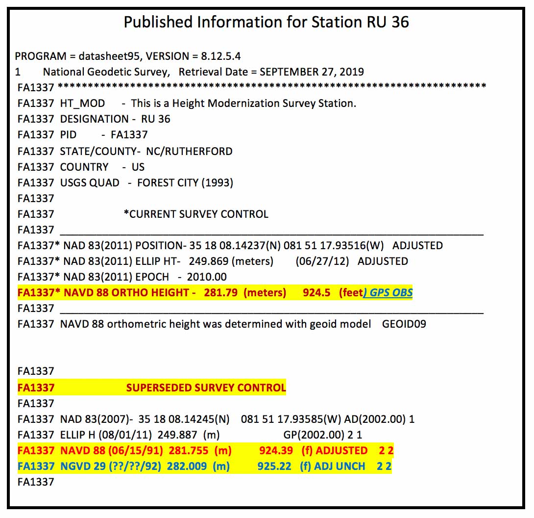
Data: National Geodetic Survey

Data: National Geodetic Survey

Also, it should be noted that the current version of VERTCON is based on published NAVD 88 heights as of a certain date. If a station has been readjusted since VERTCON 3.0 was generated, then the difference between the modeled value and the published value may be different. The actual difference will depend on how much the newly published orthometric height differs from the previously published orthometric height. If a single station’s height changed due to being disturbed by a local phenomenon such as road construction equipment, then the VERTCON value should still be valid.

However, if the heights of several stations in a region changed due to a regional phenomenon such as crustal movement and/or a large adjustment distribution correction due to a regional vertical control network adjustment, then the VERTCON values may not provide the best estimate of the difference between the two datums.

An example of this is provided in the boxes titled “Published Information for Station R 1036” and “Converting from NGVD 29 to NAVD 88 – Output Solution for Station R 1036.” Station R 1036’s NAVD 88 height was updated in September 2019 ,which was after the creation of the VERTCON model. This means that the latest published NAVD 88 height (6.269 m) would not have been used in the model. The newly adjusted NAVD 88 height and the superseded height differ by –23.7 cm (6.269 m – 6.506 m). In this case, this is not an isolated change of a single station’s published height. The adjusted heights of the stations in the region have all changed due to apparent crustal movement and/or a large distribution correction due to a vertical network adjustment.

Published Information for Station R 1036

Data: National Geodetic Survey

Data: National Geodetic Survey

The box titled “Converting from NGVD 29 to NAVD 88 – Output Solution for Station R 1036” provides the converted NAVD 88 height using the NCAT tool. The converted NGVD 29 to NAVD 88 value differs by 23.5 cm (6.504 m minus 6.269 m). Which is expected because the newly published height and superseded height differ by 23.7 cm. It agrees to within 2 mm of the previously published NAVD 88 height (6.506 m minus 6.504 m = 0.002 m). Once again, this is not implying that there is something wrong with the VERTCON model. It’s only to note the limitations of the model. Users need to remember that it is a model and it does not produce geodetic quality coordinate values.

Converting from NGVD 29 to NAVD 88 – Output Solution for Station R 1036
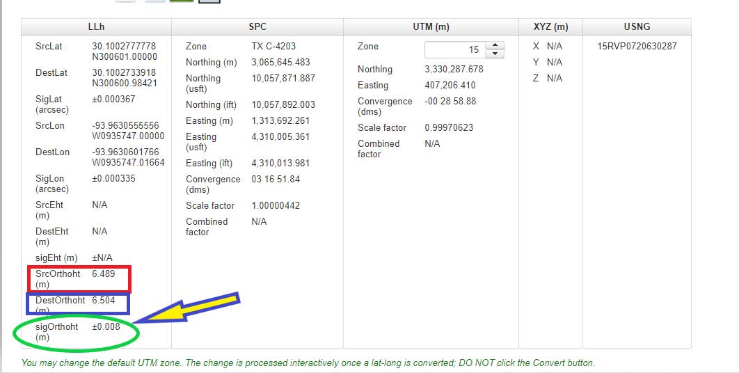
Image: National Geodetic Survey

Image: National Geodetic Survey

Users can also convert from other vertical datums published by NGS. These datums include:

  • Puerto Rico Vertical Datum of 2002 (PRVD 02)
  • American Samoa Vertical Datum of 2002 (ASVD 02)
  • Northern Mariana Vertical Datum of 2003 (NMVD 03)
  • Guam Vertical Datum of 2004 (GUVD 04)

An example of converting a station with a PRVD 02 orthometric height to a Local Tide (LT) value is provided is the boxes titled “Converting from PRVD 02 to Local Tide (LT) – Input Parameters“ and “Converting from PRVD 02 to LT – Output Solution for Station 11 R RESET.”

Converting from PRVD 02 to Local Tide (LT) – Input Parameters
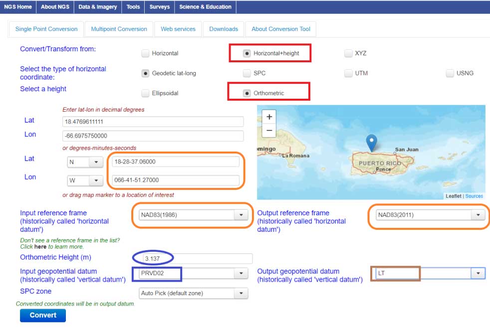
Image: National Geodetic Survey

Image: National Geodetic Survey

Converting from PRVD 02 to LT – Output Solution for Station 11 R RESET
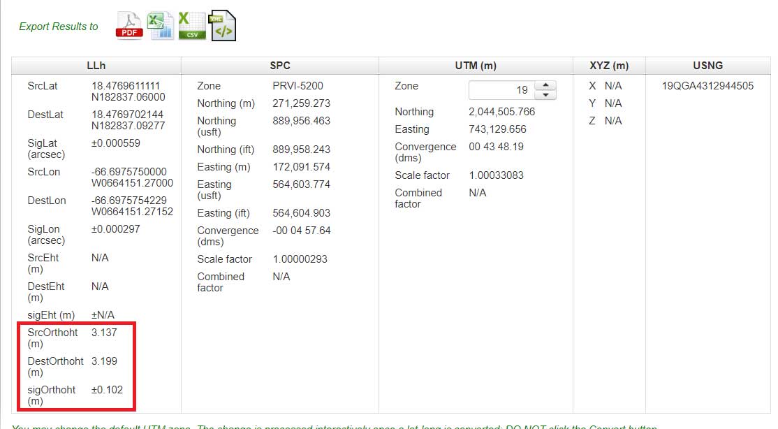
Image: National Geodetic Survey

Image: National Geodetic Survey

Notice that the difference between the PRVD 02 and converted LT value differ by 0.062 m but the accuracy estimate is +/- 0.102 m.

In my opinion, the VERTCON model and the NCAT tool are extremely helpful tools to the surveying and mapping community. NGS is developing these models and tools to support the implementation of the North American-Pacific Geopotential Datum of 2022 (NAPGD2022). I would encourage all users to download the technical report and perform a couple of conversions in your area of interest.

NGS would like individuals to use the beta products and services and provide feedback. What do you like about the tool and its features? What would you like changed or added to the service? I hope everyone will try the beta version and contact NGS with their comments.

NGS is in a listening mode and wants to develop models and tools to assist users in their transition to the new reference frames in 2022. This is your opportunity to let NGS know what you need (desire) to implement the new reference frames.

Publicerad den Lämna en kommentar

GPS III production update: On the road to a refreshed constellation

Thermal Vacuum testing verifies that a satellite can operate in space’s extreme environment. (Photo: Lockheed Martin)

Thermal Vacuum testing verifies that a satellite can operate in space’s extreme environment. (Photo: Lockheed Martin)

With GPS III SV01 and SV02 now on orbit, GPS III satellites continue to roll off the production line at Lockheed Martin’s GPS III Processing Facility near Denver.

Johnathon Caldwell, Lockheed Martin Space’s vice president for navigation systems, provided GPS World with an update to the entire GPS III family.

SV01. The first GPS III satellite is in a holding state pending readiness by 2SOPS [the Second Space Operations Squadron] to take the vehicle onto the system for operational checkout, a transfer expected to take place later this year, Caldwell explained. The satellite completed on-orbit testing in July.

“We’re in the process of getting the 2SOPS crews trained up to operate a GPS III vehicle,” Caldwell said. “By the end of this year, they will be able to take [SV01] into the constellation and start flying it as a live, set-healthy vehicle.”

SV02. Launched Aug. 22, SV02 is following in the footsteps of its older sibling, with a quiet checkout and no major findings. Like SV01, once it completes testing, it will stay in temporary holding until 2SOPS is ready to bring it into the constellation.

SV03. On May 27, the Air Force declared SV03 available for launch. It is now in final preparations for shipment, with an expected launch date in January 2020 aboard a Falcon 9 rocket.

SV04. The Air force declared SV04 available for launch; it is now in storage awaiting a launch date.

SV05. The fifth satellite is wrapping up environmental tests. Lockheed Martin anticipates that it will be available for launch early next year.

SV06. The satellite has been moved into the thermal vacuum testing chamber and begun a rigorous testing campaign before it meets the harsh environment of space.

SV07, SV08 and SV09 are on the assembly line.

GPS IIIF Satellites. In 2018, the Air Force selected Lockheed Martin to build 10 GPS IIIFs, adding new features and resiliency to the original GPS III satellite design. The company has been on the path to meet the critical design review for the GPS IIIF spacecraft, which is due to take place next spring.

Publicerad den Lämna en kommentar

LORD’s SensorConnect software improves MicroStrain data collection

SensorConnect Logo

LORD Corporation has released the latest version of its SensorConnect sensing software, featuring significant updates that support sensor management and data collection and visualization for MicroStrain inertial products.

The update is designed to fully replace the inertial data collection and visualization capabilities in MIP Monitor. MIP Monitor will continue to be available on the website, but will no longer be updated to support new products.

“We’re excited to support users with a desktop software solution that provides a better experience for our inertial users,” said Justin Bessette, manager, Technology and Innovation, LORD Sensing, MicroStrain. “It is important for us to provide users a single tool to collect data and visualize output from both wireless and inertial product lines, side-by-side.”

In previous updates, SensorConnect offered basic support for inertial products. Release 12.0.9 marks the inclusion of all features necessary for inertial users to fully migrate from MIP Monitor to SensorConnect. Users will find all MIP Monitor features available in a more modern and flexible interface, with improved feedback. SensorConnect users will benefit from regular updates, new features and user experience improvements. Additional updates featured as a part of 12.0.9 include storing and displaying matrix, quaternion data and storing, and displaying data valid flags.

New features important for inertial users who are new to SensorConnect include:

  • Inertial Save/Load Settings (v10.4.9)
  • Packet Monitor (v9.17.4)
  • Record Packets to File (v10.4.9)
  • Support for Double-Precision (v10.0.8)
  • Initialize/Reset Estimation Filter (v9.9.2)
    • Initialize/Reset Estimation Filter screen added to enable inertial users to more easily configure, initialize and troubleshoot the device’s estimation filter

Documentation for inertial customers and release notes have been added to the MicroStrain website.

SensorConnect for MIP Monitor Users is designed for inertial users who are accustomed to using MIP Monitor for configuration, sensor management, data monitoring and data collection.

SensorConnect offers the capability to accomplish the same tasks with additional functionality compared to MIP Monitor. Current MIP Monitor users should switch to SensorConnect, the company said.

Publicerad den Lämna en kommentar

FAA certifies UPS Flight Forward as an air carrier

The United States Federal Aviation Administration (FAA) has awarded air carrier and operator certification to UPS Flight Forward, an unmanned aircraft system (UAS) delivery company.

Through the DOT’s UAS Integration Pilot Program, the FAA has now approved a Part 135 operating certificate for UPS Flight Forward. This allows the company to perform revenue-generating package delivery activities within federal regulations.

UPS Flight Forward may now operate multiple drones under one certificate. Under Part 135, the company can deliver vital healthcare supplies including by flying beyond visual line of sight.

The UPS subsidiary immediately launched the first drone delivery flight by any company under Part 135 Standard at WakeMed’s hospital campus in Raleigh, N.C. That flight, using a Matternet M2 quadcopter, was flown under a government exemption allowing for a beyond-visual-line-of-sight (BVLOS) operation, also a first in the U.S. for a regular revenue-generating delivery.

UPS said it has proven the need for drone delivery in healthcare operations, where the shortest time in transit can improve efficiency and help healthcare professionals better serve patients.

The medical delivery program at WakeMed is the result of testing conducted by UPS and Matternet in August of 2018 as part of their participation in the UAS Integration Pilot Program (UAS IPP).

UPS partnered with Matternet to launch its healthcare delivery service on the WakeMed campus. The revenue-generating service demonstrated the business case for drone delivery of medical products and specimens.

Now, with its Part 135 Standard certification, UPS is ready to build on this application and expand to a variety of critical-care or lifesaving applications.

Photo: UPS

Photo: UPS

“This is history in the making, and we aren’t done yet,” said David Abney, UPS chief executive officer. “Our technology is opening doors for UPS and solving problems in unique ways for our customers. We will soon announce other steps to build out our infrastructure, expand services for healthcare customers and put drones to new uses in the future.”

The company will initially expand its drone delivery service further to support hospital campuses around the country, and to provide solutions for customers beyond those in the healthcare industry.

Part 135 Standard certification enables UPS to integrate drones into the UPS logistics network, creating potential for new applications in many industries. The company has a long-term plan with milestones that include:

  • expansion of the UPS Flight Forward delivery service to new hospitals and medical campuses around the country.
  • rapid build-out of ground-based, detect-and-avoid (DAA) technologies to verify drone safety, while enabling future service expansion.
  • construction of a centralized operations control center.
  • regular and frequent drone flights beyond the operator’s visual line of sight.
  • partnerships with additional drone manufacturers to build new drones with varying cargo capacities.
  • adding new services outside of the healthcare industry, including the transport of special commodities and other regulated goods.

“UPS is committed to using technology to transform the way we do business,” said Scott Price, UPS chief transformation and strategy officer. “UPS’s formation of a drone delivery company and application to begin regular operations under this level of certification is historic for UPS and for the drone and logistics industries.”

As a participant in the U.S. Transportation Department’s Unmanned Aircraft Systems Integration Pilot Program, the North Carolina Department of Transportation (NCDOT) partnered with UPS Flight Forward. As the operator, they have been engaged in delivery of healthcare supplies around a major hospital campus in Raleigh, North Carolina. The flights have focused on the delivery of blood for potentially life-saving transfusions, as well as other medical samples for lab work.

The company demonstrated that its operations met the FAA’s rigorous safety requirements to qualify for an air carrier certificate. This is based on extensive data and documentation, as well as test flights.

Publicerad den Lämna en kommentar

Skward releases airspace maps, access for drone pilots

The drone operations management platform provides information on 3D vertical structures and obstacles, and access to digital airspace, to improve drone flight safety.

Skyward, a Verizon company, has introduced Advanced Airspace Intelligence for drone pilots.

Skyward’s drone airspace maps provide airspace data combined with essential ground intelligence including 3D views of key structures, transmission lines, and more than a million vertical obstacles.

The platform also provides access to LAANC, the Low Altitude Authorization and Notification Capability program provided by the U.S. Federal Aviation Administration.

Drone pilots in the field need to know how the surrounding area, including infrastructure, could affect flight, and Skyward offers this critical safety data to all users.

Skyward introduces Advanced Airspace Intelligence from SkywardIO on Vimeo.

“Showing airspace is important, but it’s only part of the picture. The more intelligence that is available to understand how an area will affect the flight, the less risk a pilot has in the field,” said Mariah Scott, president of Skyward. “Skyward Airspace Intelligence is the only solution that provides easy-to-understand data for things like transmission lines, runways, over a million vertical obstacles, and a 3D view of key structures. It’s the next best thing to physically being in the field.”

In addition to comprehensive airspace information, the following data is now available for situational awareness:

  • Vertical structure obstacles (over one million structures identified from the FAA and FCC databases)
  • Major power transmission lines
  • Airports
  • Runways
  • Heliports
  • U.S. and Canadian National Parks
  • Stadiums
  • Hospitals
  • Schools
  • Pedestrian walking paths

Skyward Airspace Intelligence is part of a complete workflow that enables pilots mitigate weather, environment and business-specific risks.

Image: Skyward

Image: Skyward

Publicerad den Lämna en kommentar

ESA tests 5G positioning with GNSS + UWB drive

News from the European Space Agency

A pair of testbed vehicles went out on the road in Germany to simulate the way we are all likely to be using 5G positioning services in the future. The field test focused on assessing the performance of highly precise hybrid satellite/terrestrial positioning for autonomous vehicles, drones, smart cities and the internet of  things (IoT).

The two vehicles were driven for a week around Munich and the surrounding area in a variety of environments, from the open-sky terrain surrounding the German Aerospace Center DLR’s site in Oberpfaffenhofen to the deep urban canyons of the city’s dense Maxverstadt district.


As they drove, they combined a broad range of on-board systems to measure their positions and share them with one another, performing ongoing vehicle-to-vehicle ranging to simulate future 5G operating standards.

The on-board systems included multi-constellation satellite navigation (combining Europe’s Galileo, the U.S. GPS, Russian GLONASS and Chinese BeiDou), incorporating localized high-accuracy correction, and 4G Long-Term Evolution (LTE) and ultra-wideband (UWB) terrestrial wireless broadband communication.

The coming of the next generation of mobile phone networks, 5G, promises much faster, more stable connectivity based on higher bandwidths and frequencies, but the ability to download a full movie in a matter of seconds is only the start. The increased capabilities will also open up a new range of services, many of them based around localization.

From smart traffic management to asset tracking to personalized drone-based delivery, our receivers’ ability to know where they are and share those positions with the wider network will be vital.

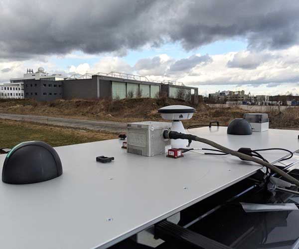
Close-up view of Car A with GNSS and LTE antennas. (Photo: ESA)

Close-up view of Car A with GNSS and LTE antennas. (Photo: ESA)

“The first step required is understanding what the upcoming disruptive applications are, and to identify the potential requirements associated with them,” said Riccardo de Gaudenzi, who leads ESA’s Electrical Department in its Directorate of Technology, Engineering and Quality.

“For these use cases, positioning and timing are key elements. Therefore positioning, navigation and timing (PNT) aspects, provided via GNSS like Galileo, the terrestrial communication infrastructure and hybridization of technologies, are extremely important.”

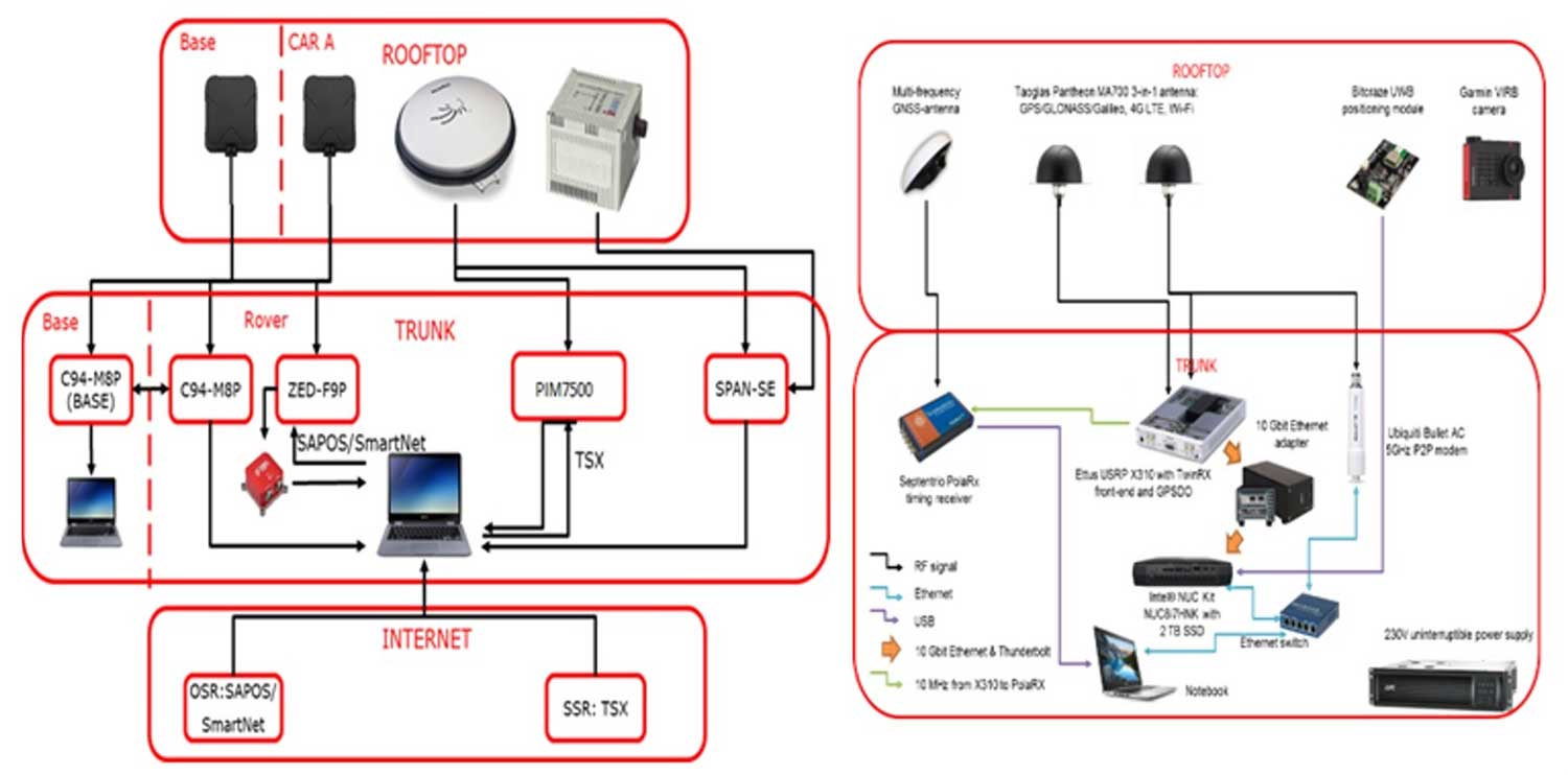
The testbed vehicles combined a broad range of on-board systems, including multi-constellation GNSS, incorporating localized high-accuracy correction. (Image: ESA)

The testbed vehicles combined a broad range of on-board systems, including multi-constellation GNSS, incorporating localized high-accuracy correction. (Image: ESA)

Today we rely largely on satellite navigation to determine where we are. But our smartphones quietly blend satnav with other data sources to sharpen the accuracy of their results. That is why, for example, when you turn off your phone’s Wi-Fi receiver, your smartphone will warn you its mapping will become less accurate – it is also using Wi-Fi maps as a reference source.

With 5G, this trend of hybrid positioning will accelerate. Multiple GNSS constellation will be employed to increase accuracy, along with localized correction systems. In addition, the 5G cell network will provide additional corrections to enhance the GNSS localization accuracy and to complement GNSS when satellites are not visible.

This 5G “new radio” positioning accuracy will be enhanced by using steerable antennas on both the base station and the user terminal.

The testbed vehicles combined a broad range of on-board systems, incorporating localized high-accuracy correction and LTE 4G and ultra-wide-band terrestrial wireless broadband communication, to measure their positions and share them with one another and perform ongoing vehicle-to-vehicle ranging to simulate future 5G operating standards. (Image: ESA)

The testbed vehicles combined a broad range of on-board systems, incorporating localized high-accuracy correction and LTE 4G and ultra-wide-band terrestrial wireless broadband communication, to measure their positions and share them with one another and perform ongoing vehicle-to-vehicle ranging to simulate future 5G operating standards. (Image: ESA)

And because positioning performance will have to remain at the same high standard as user receivers move around — whether they be people, cars, shared bikes or drones — additional positioning solutions will also be employed, such as inertial sensors or device-to-device relative positioning.

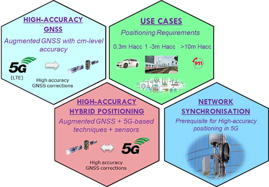
Areas where ESA is contributing to 3GPP standardisation efforts. (Image: ESA)

Areas where ESA is contributing to 3GPP standardisation efforts. (Image: ESA)

Miguel Manteiga Bautista, head of ESA’s GNSS Evolution and Strategy Division in the Agency’s Directorate of Navigation, explains, “For the hybrid positioning field-tests, ESA and its partners set up a collaboration with Deutsche Telecom for use of its 4G network in Munich including relevant information for positioning, and NovAtel, who provided state-of-the-art GNSS equipment and correction services, such as the satellite-based TerraStar-X.”

ESA oversaw this initial field-test campaign as part of its 5G GNSS Task Force, coordinated with the European Commission and the European GNSS Agency, through the Horizon 2020 Framework Programme for Research and Innovation in Satellite Navigation. It was undertaken by DLR and the GMV company, with contributions by engineers from NovAtel, u-blox and Deutsche Telekom as well as ESA.

In 2016 ESA’s European GNSS Evolution Programme took the initiative to shape the support of high-accuracy positioning services in 4G and 5G networks, to contribute to the 3rd Generation Partnership Project, 3GPP, worldwide standardisation effort.

The next phase of this project, called GNSS Integration into 5G wireless networks or GINTO5G, involves thorough processing of all the data gathered during the field test campaign, leading into additional field experiments.

This pair of testbed vehicles went out on the road in Germany to simulate the way we are all likely to be using 5G positioning services in the future. (Photo: ESA)

This pair of testbed vehicles went out on the road in Germany to simulate the way we are all likely to be using 5G positioning services in the future. (Photo: ESA)