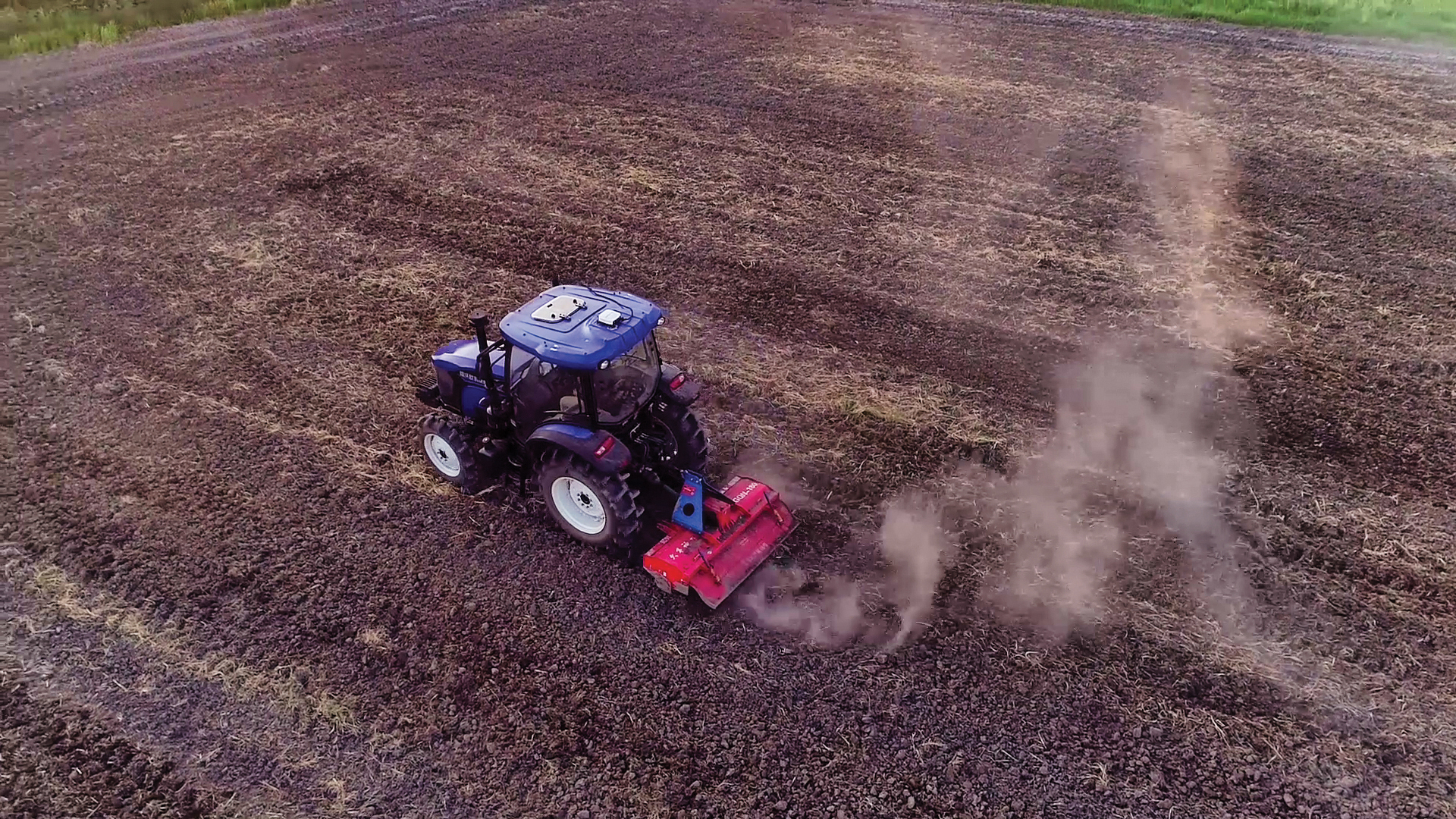
PRECISION AGRICULTURE reduces inputs of seed, water, fertilizer, pesticides and fuel. (Photo: CHCNAV)
Precision agriculture refers to the ability of farmers to observe, measure and respond more precisely to the variability of soil and crop characteristics within and between fields by using maps of these characteristics and GNSS navigation. It enables them to reduce inputs of seed, water, fertilizer, pesticides and fuel while increasing outputs. Adoption of precision agriculture technology and practices has increased steadily over the past three decades and now covers the majority of U.S. farmland.
We asked three companies that manufacture GNSS receivers optimized for precision agriculture about their challenges and plans.
— Matteo Luccio, Editor-in-Chief
Roland Moelder, Product Manager
What are the key challenges for precise positioning in agriculture?
One of the main concerns is the impact of obstructions — both natural, such as tree canopy and topographies, and manmade, such as buildings, silos, etc. The mounting location of the GNSS antenna on an agricultural vehicle or implement can emphasize multipath effects and limit GNSS signal availability.
Our solution for these challenges is the use of a multi-frequency receiver. In this case, the increased number of tracked GNSS signals (from GPS, Galileo, GLONASS and BeiDou), as provided by the latest Hemisphere GNSS technology used with the A631 Smart Antenna product, allows the receiver to overcome challenging conditions to ensure a stable and robust positioning solution. For example, if a tree line blocks a part of the sky at the headland of the field, it can be compensated for with additional satellite signals available outside of the blocked area, so that guidance, automated steering and application control are not interrupted. Dust and vibrations are not an issue for us due to the rugged design of the A631 GNSS Smart Antenna. However, depending upon the radio link used, long-distance RF communications for real-time kinematic (RTK) corrections can become a limiting factor. In this case, we often propose using RTK corrections over NTRIP or considering our Atlas L-band correction service for the as an RTK-like alternative.
What is the requirement for start-up time?
Although farmers spend hours in the field during the season, the planting and harvesting windows are limited; therefore, time is critical. The requirement from farmers is to be ready to go when they start their machine. During busy times in the season, farmers often leave their equipment in the field, so startup times may only be a few minutes. We meet this requirement with our startup times for SBAS and RTK corrections and the Atlas AutoSeed feature for L-band corrections. Atlas AutoSeed allows users to suspend Atlas use for any period of time, and upon returning to their last location, the Atlas system uses AutoSeed to rapidly reconverge to a high-accuracy converged position.
What is the accuracy requirement for planting?
Especially row crop planting over what we refer to as broad acre farming requires accuracy to within a few inches, which we offer with our Atlas H10 correction service. Depending upon the farming practices used (such as controlled traffic or inter-row applications), these demands are not only for accuracy, but also for repeatability of the positioning solution.
Another area that demands high accuracy is the production of specialty crops. Per our experience, this farming practice requires sub-inch accuracy and repeatability, which we meet with our RTK solutions.
What is the difference between Atlas and Atlas Basic?
We think of Atlas Basic as a global solution comparable to the different regional offerings for SBAS corrections in terms of accuracy. This means a radius 95% pass-to-pass (R95 P2P) accuracy of around 30 cm with absolute accuracy in the submeter area. We feel that this meets the “basic” needs for all precision agriculture applications.
If a customer is looking for higher accuracies, we offer the H30 and H10 Atlas Correction Services. For comparison, Atlas H30 provides R95 P2P accuracy of 15 cm, and H10 provides R95 P2P accuracy of 4 cm.
Besides your GNSS receivers and corrections services, what hardware, software and services do you provide for precision agriculture?
We announced our new MaveriX precision agriculture solution in September 2021. It uses our recognized A631 Smart Antenna and provides a complete precision agriculture solution combined with the M7 and M10 terminals, eDriveM1 steering controller, ESi2 electric steering wheel and AC110 application controller. The MaveriX precision agriculture application software, which runs on our MaveriX terminals, is the centerpiece of the system. The first production systems are being used by customers in North America this spring.
Ling Hu, Precision Agriculture Business Development Manager
What are the key challenges for precise positioning in agriculture?
Normally in the agricultural field, the environment is harsh (mud, slopes, shocks), which requires the system to be rated IP65 and above and vibration resistant. In some areas, the signal coverage of cellular phones may be insufficient. When that is the case, a UHF modem-type communication is more commonly used with a distance constraint related to the propagation of UHF signals, strongly related to the quality of the installation of the GNSS base station (height of the UHF antenna, gain, immediate environment of the station). Our NX510 SE overcomes that issue by integrating two communication modes, 4G and UHF.

CHCNAV’S GNSS RECEIVERS can be easily switched between tractors. (Photo: CHCNav)
Is planting the application that requires the highest accuracy? What accuracy can you consistently provide?
Certainly, planting requires the highest accuracy of 2.5 cm from pass to pass. With a stable GNSS RTK correction, centimeter accuracy can be provided reliably.
What is the requirement for startup time? What do you deliver?
The startup and initialization of the system should take as little time as possible and is usually done within 1 to 2 minutes from cold start. Farmers usually start their system when they drive the tractor out of the shed and are therefore ready to work as soon as they arrive in their field. Warm start (reacquisition + RTK fixed) is more important in case of obstacles or loss of the RTK correction used by the customer, when using the auto-steering/guidance system in the field. It is typically about 10 seconds.
Besides your GNSS receivers, do you provide any additional hardware, software or services (such as support and training) for precision agriculture?
Our NX510 autopilot kit consists of a receiver, display, motor, angle sensor, camera and accessories, so users can start working immediately without purchasing additional options.
In addition to automated steering systems, CHCNAV also provides complementary solutions that allow farms to be autonomous in terms of GNSS RTK corrections. These solutions consist of GNSS base stations with an integrated or external radio modem and GNSS NTRIP stations for connection over 4G. Individual GNSS stations can be networked using our CPS Net software, which can be operated by a group of farmers, agricultural cooperatives or tractor dealers. Training and user support is provided by our network of authorized agricultural resellers to ensure the closest possible service to our users.
Wang Xiaohui, Technical Director, Antenna Department
What are the key challenges for precise positioning in agriculture?
Obtaining accurate position information in real time requires real-time kinematic (RTK) positioning. There are many ways to obtain differential data. One is to establish a reference station and broadcast differential data through short-distance communication methods. This method’s disadvantage is the high cost of stations and the limited transmission distance. Another is to broadcast RTK data through an LTE network. This is convenient, but if the LTE signal coverage is poor, RTK positioning may not be achieved. A third method is to rely on satellite-based augmentation. This is independent of ground communication equipment, but has a relatively long convergence time and may be greatly affected by signal occultation.
Agricultural machinery must work in harsh environments, such as extreme heat, severe cold and strong vibrations. Consequently, the antenna must be enclosed in a robust housing with excellent protection to guarantee long-time outdoor work.
When agricultural machinery operates near densely packed and tall trees, positioning accuracy will be significantly affected. Limits on the size and cost of antennas for agricultural machinery prevent the use of choke-ring structures. Therefore, the key to achieving high-precision positioning lies in how to receive more satellite signals and avoid multipath interference in a small antenna size.
How can the antenna help with these challenges?
Harxon’s X-Survey antenna is highly integrated and multi-functional. It embeds antennas for GNSS (GPS, GLONASS, BeiDou, Galileo, QZSS, NavIc, other regional systems and SBAS), 4G, Bluetooth/Wi-Fi 900M/2.4G radio, and other frequencies. The X-Survey enables users to choose the most appropriate way for them to acquire differential data — LTE, Wi-Fi, radio or SBAS — making high-precision positioning possible in most environments.
Harxon has designed many high-precision antennas with different structures for various application environments, including those that are waterproof and dustproof and those that can withstand very high and low temperatures and violent vibrations.
Additionally, Harxon’s antennas adopt unique cross-polarization suppression technology, with good circular polarization characteristics, providing effective suppression performance for multipath signals.
How does Harxon support TerraStar correction services?
Harxon’s TS112 PRO Smart Antenna provides reliable positioning solutions for agricultural automatic guidance. It can obtain RTK-level positioning information by receiving correction data from the embedded UHF radio or its GSM modem. Also, TS112 PRO embeds a Hexagon | NovAtel OEM GNSS module, and TerraStar multi-constellation corrections are available globally on this compatible module. TerraStar corrections are available as a termed subscription from Hexagon | NovAtel.
Gilla detta:
Gilla Laddar in …